
So, finally I’ve had the time to kick off my long awaited home automation project – my excuse to play with the whole “Internet of Things” (IoT). In the long term I’d like to get my local school involved – bringing IoT to the community. As my day job requires poking around with a lot of fun technologies, protocols and python (hacker not programmer) all in the name of datacentre automation (a.k.a. cloud computing to marketing folks out there) I’m going to leverage these skills to create a robust home automation ecosystem. DL360s and iLOs will be replaced with Raspberry Pis and Arduinos.
There are many great blogs out there on the inter-tubes that have inspired me such as JeeLabs , LowPowerLabs and Martin’s corner on the web. These guys are the experts! Please consult these sites if you wish to build your own. I’m building for the sake of learning, fantastic ready made systems already exist now. This blog will merely be presenting the discoveries that I think may interest others whilst on my journey…
Playing with low power RF communications
If you’re wondering why I don’t just stick to WiFi for communications the answer is simply power and range! WiFi modules are power hungry in comparison to simpler RF devices. Not all devices to be linked to the internet will be near a power source so it will be necessary to run these from batteries – e.g. plant monitors, remote temperature sensors etc. Ultimately these battery devices will send their information to the internet through a gateway Raspberry Pi (RPi). The RPi will have both internet connectivity and RF connectivity.
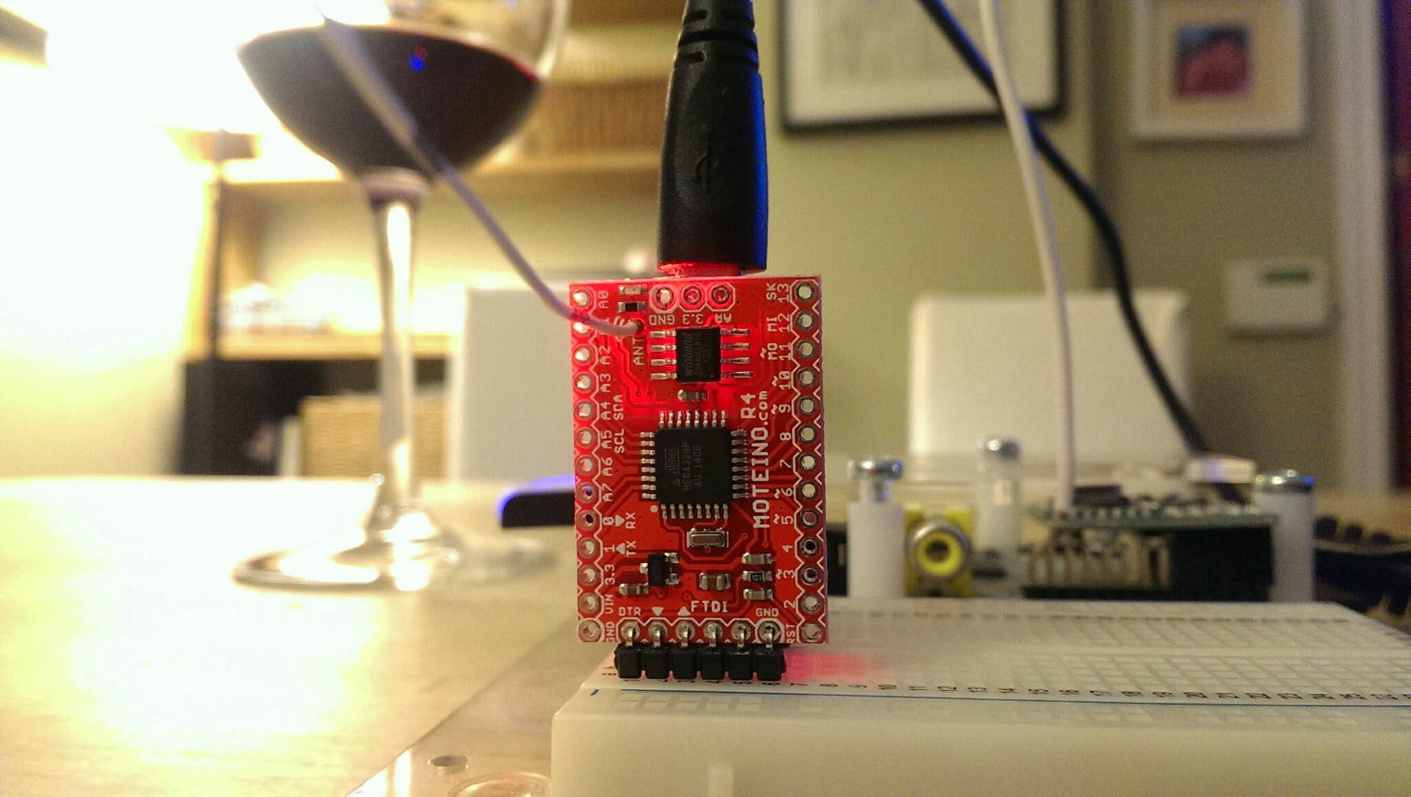
The first challenge that I had was to evaluate some low cost, ready made RF devices which included a couple of Moteinos (these are superb), from Felix at LowPowerLabs.com and the RFM12PiV2 from the OpenEnergyMonitor project. This device plugs into the Raspberry Pi and will be the gateway to the internet for all my RF based IOT devices.

As I chose RF devices from two different projects they need some tweaks to get them talking correctly to each other and that’s what the rest of this blog will cover.
What these devices both have in common is that they both use the Arduino compatible development platform based on the ATMega328 chip. As a result they can both be programmed using the Arduino IDE. The devices also have an integrated daughter board which contains the HopeRF RFM12B transceiver.
They differ in that they both run different programs (also known as sketches in the Arduino world) and their hardware clocks have also been architected slightly differently. The Moteino uses an external 16Mhz clock signal whereas the RFM12PiV2 uses the internal 8Mhz clock that is built into the ATMega328. This last piece of information is vital when syncing transmission between the devices.
I decided to use the Moteinos test sketches located here – Node and Gateway only changing the addressing and baud rate as can been see next :
Node Sketch
// Test sketch that is loaded on slave Moteinos
// It will send an encrypted message to the master/gateway every TRANSMITPERIOD
// It will respond to any ACKed messages from the master
// Every 3rd message will also be ACKed (request ACK from master).
#include <RFM12B.h>
#include <SPIFlash.h>
#include <SPI.h>b
#include <avr/sleep.h>

#define MYID 123 // node ID used for this unit
#define NETWORKID 50
#define GATEWAYID 1
#define FREQUENCY RF12_433MHZ //Match this with the version of your Moteino! (others: RF12_433MHZ, RF12_915MHZ)
#define KEY "ABCDABCDABCDABCD"
int TRANSMITPERIOD = 500; //transmit a packet to gateway so often (in ms)

#define SERIAL_BAUD 115200
#define ACK_TIME 50 // # of ms to wait for an ack

char input = 0;
RFM12B radio;
SPIFlash flash(8, 0xEF30); //EF30 for Windbond 4mbit flash
boolean requestACK = false;
byte sendSize=0;
char payload[] = "123 ABCDEFGHIJKLMNOPQRSTUVWXYZ";

void setup()
{
Serial.begin(SERIAL_BAUD);
radio.Initialize(MYID, FREQUENCY, NETWORKID, 0);
radio.Encrypt((byte*)KEY);
char buff[50];
sprintf(buff, "Transmitting at %d Mhz...", FREQUENCY == RF12_433MHZ ? 433 : FREQUENCY== RF12_868MHZ ? 868 : 915);
Serial.println(buff);
if (flash.initialize())
Serial.println("SPI Flash Init OK!");
else
Serial.println("SPI Flash Init FAIL! (is chip present?)");
}

long lastPeriod = -1;
void loop()
{
//process any serial input
if (Serial.available() > 0) {
input = Serial.read();
if (input >= 48 && input <= 57) //[0,9]
{
TRANSMITPERIOD = 100 * (input-48);
if (TRANSMITPERIOD == 0) TRANSMITPERIOD = 1000;
Serial.print("\nChanging delay to ");
Serial.print(TRANSMITPERIOD);
Serial.println("ms\n");
}
else if (input == 'd') //d=dump flash area
{
Serial.println("Flash content:");
int counter = 0;

while(counter<=256){
Serial.print(flash.readByte(counter++), HEX);
Serial.print('.');
}
while(flash.busy());
Serial.println();
}
else if (input == 'e')
{
Serial.print("Erasing Flash chip ... ");
flash.chipErase();
while(flash.busy());
Serial.println("DONE");
}
else if (input == 'i')
{
Serial.print("DeviceID: ");
Serial.println(flash.readDeviceId(), HEX);
}
}

//check for any received packets
if (radio.ReceiveComplete())
{
if (radio.CRCPass())
{
Serial.print('[');Serial.print(radio.GetSender(), DEC);Serial.print("] ");
for (byte i = 0; i < *radio.DataLen; i++)
Serial.print((char)radio.Data[i]);

if (radio.ACKRequested())
{
radio.SendACK();
Serial.print(" - ACK sent.");
}
Blink(9,5);
}
}

int currPeriod = millis()/TRANSMITPERIOD;
if (currPeriod != lastPeriod)
{
lastPeriod=currPeriod;
//Send data periodically to GATEWAY
Serial.print("Sending[");
Serial.print(sendSize);
Serial.print("]: ");
for(byte i = 0; i < sendSize; i++)
Serial.print((char)payload[i]);

requestACK = ((sendSize % 3) == 0); //request ACK every 3rd xmission
radio.Send(GATEWAYID, payload, sendSize, requestACK);
if (requestACK)
{
Serial.print(" - waiting for ACK...");
if (waitForAck(GATEWAYID)) Serial.print("ok!");
else Serial.print("nothing...");
}

sendSize = (sendSize + 1) % 31;
Serial.println();
Blink(9,5);
}
//else { Serial.print("currPeriod = "); Serial.print(currPeriod); Serial.print(" lastPeriod = "); Serial.println(lastPeriod); }
}

// wait a few milliseconds for proper ACK to me, return true if indeed received
static bool waitForAck(byte theNodeID) {
long now = millis();
while (millis() - now <= ACK_TIME) {
if (radio.ACKReceived(theNodeID))
return true;
}
return false;
}

void Blink(byte PIN, int DELAY_MS)
{
pinMode(PIN, OUTPUT);
digitalWrite(PIN,HIGH);
delay(DELAY_MS);
digitalWrite(PIN,LOW);
}
Gateway Sketch
// Test sketch that is loaded on master Moteinos
// It will listen for any packets received from slave Moteinos
// If an ACK request message is received, it sends and ACK and also
// sends an ACKed message to the slave, ensuring that 2-way
// communication is functional on the slave Moteino

#include <RFM12B.h>

#define SERIAL_BAUD 115200
#define NODEID 1 // network ID used for this unit
#define NETWORKID 50
#define FREQUENCY RF12_433MHZ //Match this with the version of your Moteino! (others: RF12_433MHZ, RF12_915MHZ)
#define KEY "ABCDABCDABCDABCD" //encryption key
#define ACK_TIME 50 // # of ms to wait for an ack
uint8_t input[RF12_MAXDATA];
RFM12B radio;

void setup()
{
pinMode(9, OUTPUT);
radio.Initialize(NODEID, FREQUENCY, NETWORKID);
radio.Encrypt((byte*)KEY);
Serial.begin(SERIAL_BAUD);
char buff[50];
sprintf(buff, "Listening at %d Mhz...", FREQUENCY == RF12_433MHZ ? 433 : FREQUENCY== RF12_868MHZ ? 868 : 915);
Serial.println(buff);
}

byte recvCount = 0;

void loop()
{
if (radio.ReceiveComplete())
{
if (radio.CRCPass())
{
digitalWrite(9,1);
Serial.print('[');Serial.print(radio.GetSender(), DEC);Serial.print("] ");
for (byte i = 0; i < *radio.DataLen; i++)
Serial.print((char)radio.Data[i]);

if (radio.ACKRequested())
{
byte theNodeID = radio.GetSender();
radio.SendACK();
//when a node requests an ACK, respond to the ACK and also send a packet requesting an ACK
//This way both TX/RX NODE functions are tested on 1 end at the GATEWAY
Serial.print(" - ACK sent. Sending packet to node ");
Serial.print(theNodeID);
delay(10);
radio.Send(theNodeID, "ACK TEST", 8, true);
Serial.print(" - waiting for ACK...");
if (waitForAck(theNodeID)) Serial.print("ok!");
else Serial.print("nothing...");
}
delay(5);
digitalWrite(9,0);
}
else Serial.print("BAD-CRC");

Serial.println();
}
}

// wait a few milliseconds for proper ACK to me, return true if indeed received
static bool waitForAck(byte theNodeID) {
long now = millis();
while (millis() - now <= ACK_TIME) {
if (radio.ACKReceived(theNodeID))
return true;
}
return false;
}
Downloading the sketch to the Moteino
This is straight forward by connecting the Moteino directly to a PC running the Arduino IDE and use the standard Arduino process. These devices also have a very useful wireless programming capability which is covered here.

Downloading the sketch to the RFM12PiV2 (using the Raspberry Pi)
This process is a little bit trickier. We need to compile the gateway sketch using the Arduino IDE first and then locate the compiled bin file.
Enable verbose output in the preferences of the Arduino IDE as shown below :
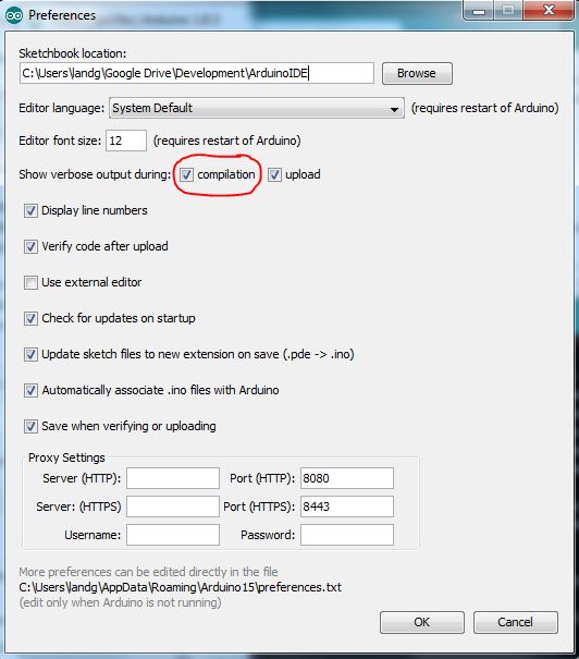
Now when you compile the sketch the output window will give you the location of the compiled file that you will need to transfer to the Raspberry Pi.

Ensure that the serial port on the Raspberry Pi has been enabled as detailed here.
The last piece in this puzzle – How to upload new code from the Raspberry Pi to the RFM12PiV2 – has already been documented here but will also be outlined again below :
$ sudo apt-get update
$ sudo apt-get install -y arduino python-dev python-rpi.gpio
$ git clone https://github.com/mharizanov/avrdude-rpi.git
$ cd avrdude-rpi
$ sudo cp autoreset /usr/bin
$ sudo cp avrdude-autoreset /usr/bin
$ sudo mv /usr/bin/avrdude /usr/bin/avrdude-original
$ sudo ln -s /usr/bin/avrdude-autoreset /usr/bin/avrdude
# Change to the directory where the binary file has been copied
$ avrdude -v  -c arduino -p ATMEGA328P -P /dev/ttyAMA0 -b 38400 -U flash:w:<Enter Filename Here and remove arrow brackets>
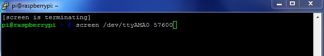
Finally, use your tool of choice to read the serial port on the Raspberry Pi – I’ve opted for screen. In the long run I’ll use a python script.
NOTE Remember that difference in clock speeds – that comes into play now. Despite the sketches both setting the baud rate to 115200, when connecting to the RFM12PiV2 which is running at half the clock speed, 8MHz instead of 16MHz, it is necessary to set the baud rate to 57600 and NOT 115200.
Now you should see something like this

Putting it all together will give you a working Moteino to RFM12PiV2 base communication system.

Taaaa – Daaaa!
Unfortunately, apparently the RFM12B module is now end of life so I’ll need to do this all over again with the RFM69 or maybe I’ll try these
🙂

Leave a comment