

Configuration of an M2 Max MacBook for use with the RaspberryPi Pico W MicroController Toolchain.
IoT pipelines have that added challenge that the “T” usually implies that the thing is a physical device.
This article details the fun and learnings I had whilst configuring my laptop to facilitate playing with the RaspberryPi’s first venture into ASIC chip development with the introduction of the RP2040 microcontroller. The RPI team have launched 2 microcontroller boards, the Pico £3.90 and the Pico_W £6.30 (prices as of 11 Oct 2023). The latter has wifi built onto the board and is the one I’m interested in playing with today.
So what is a microcontroller and what has one got to do with IoT? The RP2040 RPI Pico microcontroller is a small computer on a single integrated circuit. They have become very effective, efficient and comparatively cheap black boxes that enable physical items to be monitored, measured, instrumented and the data recorded and transmitted to another location. Or, in layperson’s terms, the RP2040 can be considered like an interpreter – it can be connected to physical devices – “Things” – and integrate them into the cloud a.k.a. the internet. So, we now have a mechanism for bidirectional sharing of data in near real-time, if required, by physical “Things”.
So, why the need for this blog… well, surprise, surprise, once again it’s Apples’ new silicon that’s inside my MacBook! The RaspberryPi foundation has created some fantastic documentation and getting started guides however these currently focus on x86 Intel based Macs and Apple has transitioned away from intel with their own proprietary CPUs. Using the official documentation in conjunction with these notes will hopefully help you to get up and running more effectively.
The main guide I am using is Getting started with Raspberry Pi Pico
So, let’s do just that, get started…
Prerequisites
A big assumption on my part is that you, the reader, has some basic developer know-how. For example, you are familiar with git, homebrew, Xcode package, vscode etc…
- Create a
picodirectory where we’ll download our SDK’s, libraries and sample code
mkdir ~/repos/pico
- Install the following 5 repositories
cd ~/repos/pico
git clone https://github.com/raspberrypi/pico-sdk.git --branch master
cd pico-sdk
git submodule update --init
cd ..
git clone https://github.com/raspberrypi/pico-examples.git --branch master
git clone https://github.com/raspberrypi/pico-extras.git --branch master
git clone https://github.com/raspberrypi/pico-playground.git --branch master
git clone https://github.com/raspberrypi/picoprobe.git --branch master
- Install Homebrew
 /bin/bash -c "$(curl -fsSL
https://raw.githubusercontent.com/Homebrew/install/master/install.sh)"
- Install the Toolchain
brew install cmake
brew tap ArmMbed/homebrew-formulae
brew install arm-none-eabi-gcc
- Apple silicon M1/M2 – install the intel emulator and accept the license
/usr/sbin/softwareupdate --install-rosetta --agree-to-license
- Configure the following paths in your default shell. Note: I’m using the fish shell here – you may need to amend this to suit the environment that you’re currently using. I had to modify my
~/.config/fish/config.fishto include these environment variables
set -gx PICO_SDK_PATH $HOME/repos/pico/pico-sdk
set -gx PICO_EXAMPLES_PATH $HOME/repos/pico/pico-examples
set -gx PICO_EXTRAS_PATH $HOME/repos/pico/pico-extras
set -gx PICO_PLAYGROUND_PATH $HOME/repos/pico/pico-playground
Our first app
- Now let’s build our first app,
blinkfor the pico_w board. Note: The default blink app in the examples repo is for the pico board without wifi – it’s LED is physically wired to a different location than the pico_w hence the need for a different blink app located in the wifi subfolder!
cd $PICO_EXAMPLES_PATH
mkdir build
cd build
cmake -DPICO_BOARD=pico_w ..
cd pico_w/wifi/blink
make -j4
- This should result in the creation of the following files
-rwxr-xr-x   1 graz  staff  263444 11 Oct 11:06 picow_blink.bin*
-rw-r--r--   1 graz  staff  670466 11 Oct 11:06 picow_blink.dis
-rwxr-xr-x   1 graz  staff  300956 11 Oct 11:06 picow_blink.elf*
-rw-r--r--   1 graz  staff  276436 11 Oct 11:06 picow_blink.elf.map
-rw-r--r--   1 graz  staff  741065 11 Oct 11:06 picow_blink.hex
-rw-r--r--   1 graz  staff  527360 11 Oct 11:06 picow_blink.uf2
The picow_blink.uf2 file is what’s required when ‘manually’ copying the program over to the pico_w. This needs a key press and hold of the BOOTSEL button AND unplugging/replugging of the USB cable to get the rp2040 into bootloader mode.
When the RP2040 is in the correct mode it should appear as an additional drive, RPI-RP2, on your MacBook in the Finder app under Locations on the left hand side.
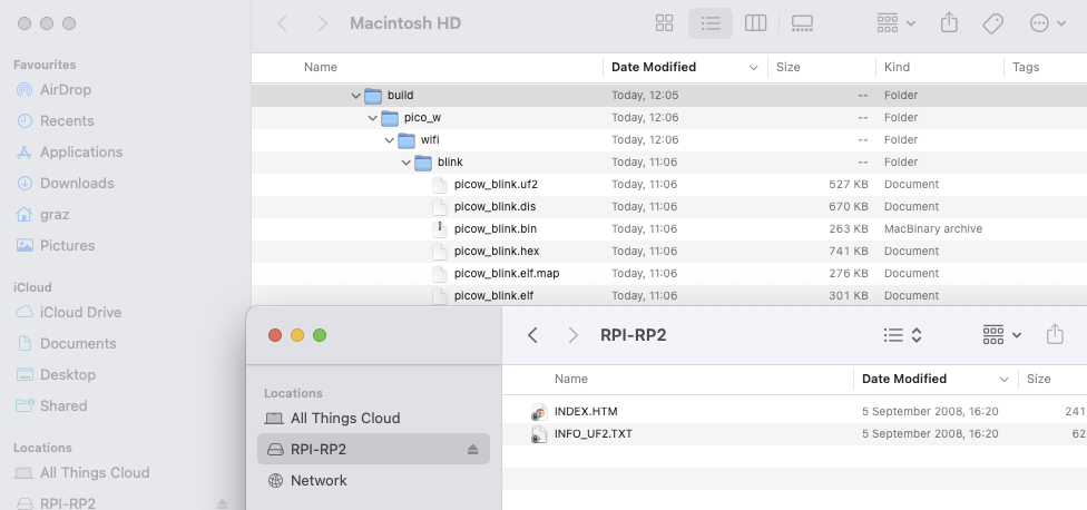
Simply drag (copy) the picow_blink.uf2 file onto the root of the RPI-RP2 drive and magic happens – the Pico_W loads the new program, disconnects from the MacBook (RPI-RP2 disappears from the attached drives), resets and runs the newly loaded program. If it has been successful you should see the onboard flashing as follows
Manual interactions, as we all know, are not always conducive to productivity – it gets very boring very fast if you’re iterating on some code changes and need to keep plugging/unplugging and pressing buttons to test these changes.
Pipeline improvements
This is where the SWD (Serial Wire Debug) port comes into play and although it will add a little more complexity to our toolchain/pipeline setup, it also improves productivity and UX (user experience).
The added complexity comes in the form of an additional debug probe with the appropriate software. An official probe could be purchased here or you could do as I have done and simply use a spare Pico as described in the offical documentation in Appendix A: Using Picoprobe
- Install some more prerequisites to ensure we can build the OpenOCD specific to the RP2040 controller – this does not work with the default Homebrew version!!! [Aside: I did get the default OpenOCD to work once I pointed it at the RaspberryPi configurations that were part of the RPI OpenOCD repository.]
brew install libtool automake libusb wget pkg-config gcc texinfo
- Download and build the RaspberryPi version of OpenOCD
cd ~/repos/pico
git clone https://github.com/raspberrypi/openocd.git --branch rp2040 --depth=1
cd openocd
fish_add_path -aP /opt/homebrew/Cellar/texinfo/7.0.3_1/bin # Note: bash shell users will need to change this e.g.  export PATH="/opt/homebrew/Cellar/texinfo/7.0.3_1/bin:$PATH"
- There’s another compilation gotcha for Apple versus Intel silicon when building out OpenOCD that’s resolved using this workaround before building…
set -gx CAPSTONE_CFLAGS "-I/opt/homebrew/Cellar/capstone/4.0.2/include/capstone -I/opt/homebrew/include" # Note: Change this to align with your preferred shell
Then carry on until you have a successful build as follows.
./bootstrap
./configure --disable-werror
make -j4
Check it runs
src/openocd
Open On-Chip Debugger 0.11.0-g8e3c38f (2023-10-11-15:32)
Licensed under GNU GPL v2
For bug reports, read
	http://openocd.org/doc/doxygen/bugs.html
embedded:startup.tcl:26: Error: Can't find openocd.cfg
in procedure 'script'
at file "embedded:startup.tcl", line 26
Info : Listening on port 6666 for tcl connections
Info : Listening on port 4444 for telnet connections
Error: Debug Adapter has to be specified, see "adapter driver" command
embedded:startup.tcl:26: Error:
in procedure 'script'
at file "embedded:startup.tcl", line 26
The above errors are expected as we have not supplied the debugger with any meaningful config…that comes later.
That’s the OpenOCD software on the Mac ready, now we have to build the application that will be loaded onto the RP2040 Pico Debugger.
- We need to download the debugger probe software from the RaspberryPi Probe repo and build the binary
cd ~/repos/pico
git clone https://github.com/raspberrypi/picoprobe.git --branch master
cd picoprobe
git submodule update --init
mkdir build
cd build
cmake ..
make -j4
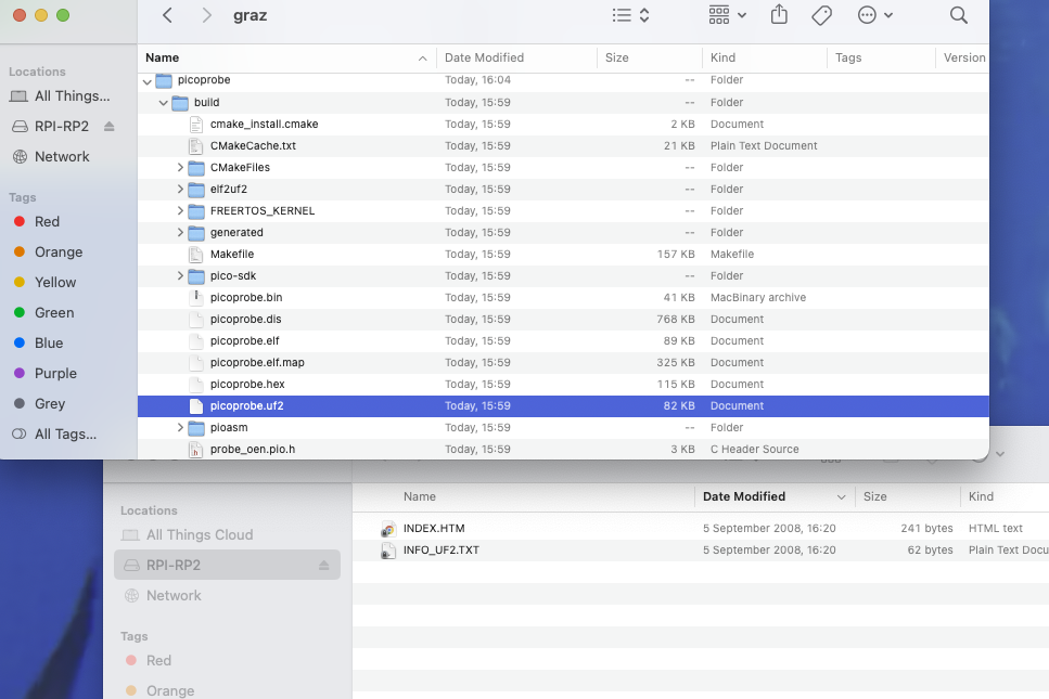
Output
[100%] Built target picoprobe
➜  build git:(master) ls -al
total 3176
drwxr-xr-x  19 graz  staff     608 11 Oct 15:59 ./
drwxr-xr-x  13 graz  staff     416 11 Oct 15:59 ../
-rw-r--r--   1 graz  staff   21126 11 Oct 15:59 CMakeCache.txt
drwxr-xr-x  18 graz  staff     576 11 Oct 15:59 CMakeFiles/
drwxr-xr-x   5 graz  staff     160 11 Oct 15:59 FREERTOS_KERNEL/
-rw-r--r--   1 graz  staff  156529 11 Oct 15:59 Makefile
-rw-r--r--   1 graz  staff    1796 11 Oct 15:59 cmake_install.cmake
drwxr-xr-x  10 graz  staff     320 11 Oct 15:59 elf2uf2/
drwxr-xr-x   3 graz  staff      96 11 Oct 15:59 generated/
drwxr-xr-x   8 graz  staff     256 11 Oct 15:59 pico-sdk/
-rwxr-xr-x   1 graz  staff   40872 11 Oct 15:59 picoprobe.bin*
-rw-r--r--   1 graz  staff  768351 11 Oct 15:59 picoprobe.dis
-rwxr-xr-x   1 graz  staff   88608 11 Oct 15:59 picoprobe.elf*
-rw-r--r--   1 graz  staff  324827 11 Oct 15:59 picoprobe.elf.map
-rw-r--r--   1 graz  staff  115023 11 Oct 15:59 picoprobe.hex
-rw-r--r--   1 graz  staff   81920 11 Oct 15:59 picoprobe.uf2
drwxr-xr-x   7 graz  staff     224 11 Oct 15:59 pioasm/
-rw-r--r--   1 graz  staff    2926 11 Oct 15:59 probe.pio.h
-rw-r--r--   1 graz  staff    3157 11 Oct 15:59 probe_oen.pio.h
Using the same process followed in Step 8 above we can now copy picoprobe.uf2 over to the pico that will be used as the Debug Probe [remember to hold the BOOTSEL button before plugging the Pico in to the USB port]
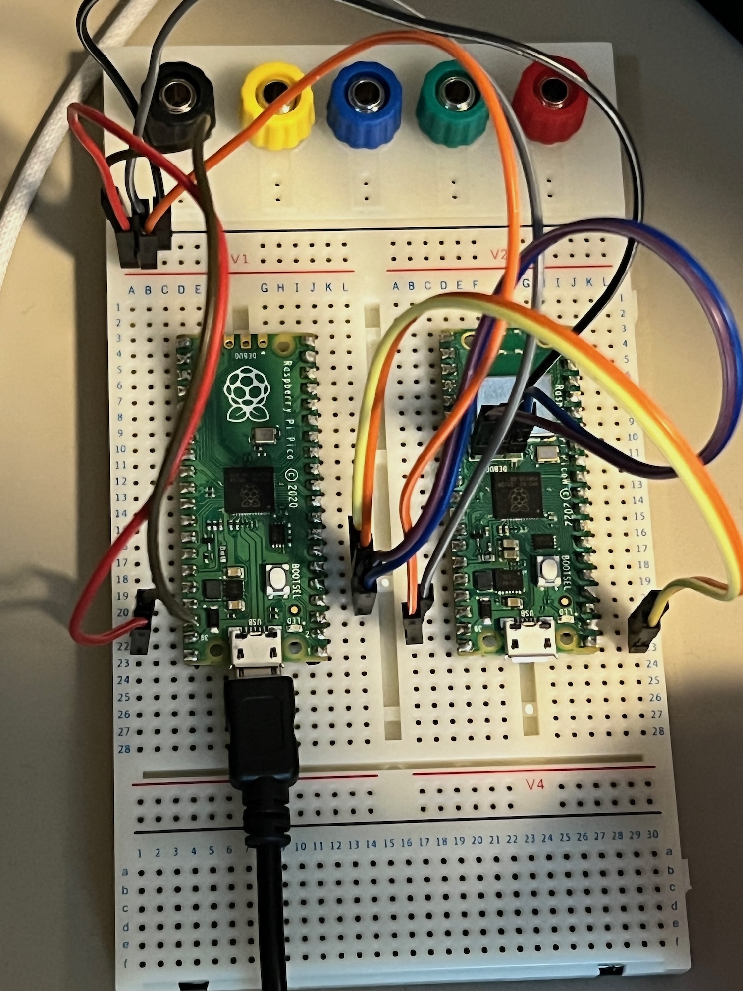
We’re almost there! Final steps are the physical wiring of the PicoProbe – ensure to follow the official documentation for this. It should look something like this
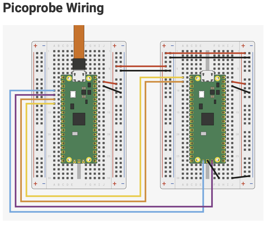
And this is what my actual setup looks like, yes I’ve got the boards the opposite way around to the diagram but the wiring is the same. Also, you may notice that in my setup the PicoProbe uses a Pico board and I’m using it to program a Pico W board.
You can use ls to see if the new probe is detected once you’ve copied the software over and ensure the USB cable is still plugged in.
If you don’t see the /dev/tty.usbmodemXXX device, try removing and reconnecting the Pico device from USB.
ls -al /dev/tty.usb*
crw-rw-rw-  1 root  wheel  0x9000002 11 Oct 17:01 /dev/tty.usbmodem102
- Install minicom, a terminal emulator program, and use it to connect to the PicoProbe’s UART (Universal Asynchronous Receiver Transmitter) port
brew install minicom
minicom -D /dev/tty.usbmodem102 -b 115200
Results in the terminal emulator running
Welcome to minicom 2.8

OPTIONS:
Compiled on Jan  1 2021, 17:45:55.
Port /dev/tty.usbmodem102, 17:01:23

Press Meta-Z for help on special keys
esc+x will get you out of this application
Now we’re ready to test an application deployment using the PicoProbe.
We’ll use the simplest of applications – Hello World – and compile this to use it’s UART rather than USB interface. Then we should be able to see the output through the PicoProbe’s UART interface.
Test run
- Build the
Hello_Worldexample to uses the serial UART instead of the USB
cd $PICO_EXAMPLES_PATH/build/hello_world/serial
make -j4
This creates the hello_serial.elf file that’s required by the PicoProbe for transfer to the target. Please remember, we’re now going to use the .elf rather than the .uf2 file as this format is required when sending it through the different interface. Both formats are created by default.
- Now let’s transfer the file using the freshly built OpenOCD application – no manual button presses or cable plugging/unplugging required!
cd $HOME/pico/openocd/tcl
../src/openocd -f interface/cmsis-dap.cfg -c "adapter speed 5000" -f target/rp2040.cfg -s tcl -c "program $PICO_EXAMPLES_PATH/build/hello_world/serial/hello_serial.elf verify reset exit"
Which will hopefully result in something like this
Open On-Chip Debugger 0.11.0-g8e3c38f (2023-10-11-15:32)
Licensed under GNU GPL v2
For bug reports, read
	http://openocd.org/doc/doxygen/bugs.html
adapter speed: 5000 kHz

Info : auto-selecting first available session transport "swd". To override use 'transport select '.
Info : Hardware thread awareness created
Info : Hardware thread awareness created
Info : RP2040 Flash Bank Command
Info : Using CMSIS-DAPv2 interface with VID:PID=0x2e8a:0x000c, serial=E6605838837F8B2E
Info : CMSIS-DAP: SWD  Supported
Info : CMSIS-DAP: FW Version = 2.0.0
Info : CMSIS-DAP: Interface Initialised (SWD)
Info : SWCLK/TCK = 0 SWDIO/TMS = 0 TDI = 0 TDO = 0 nTRST = 0 nRESET = 0
Info : CMSIS-DAP: Interface ready
Info : clock speed 5000 kHz
Info : SWD DPIDR 0x0bc12477
Info : SWD DLPIDR 0x00000001
Info : SWD DPIDR 0x0bc12477
Info : SWD DLPIDR 0x10000001
Info : rp2040.core0: hardware has 4 breakpoints, 2 watchpoints
Info : rp2040.core1: hardware has 4 breakpoints, 2 watchpoints
Info : starting gdb server for rp2040.core0 on 3333
Info : Listening on port 3333 for gdb connections
target halted due to debug-request, current mode: Thread
xPSR: 0xf1000000 pc: 0x000000ea msp: 0x20041f00
target halted due to debug-request, current mode: Thread
xPSR: 0xf1000000 pc: 0x000000ea msp: 0x20041f00
** Programming Started **
Info : RP2040 B0 Flash Probe: 2097152 bytes @10000000, in 512 sectors

target halted due to debug-request, current mode: Thread
xPSR: 0x01000000 pc: 0x00000184 msp: 0x20041f00
target halted due to debug-request, current mode: Thread
xPSR: 0x01000000 pc: 0x00000184 msp: 0x20041f00
target halted due to debug-request, current mode: Thread
xPSR: 0x01000000 pc: 0x00000184 msp: 0x20041f00
target halted due to debug-request, current mode: Thread
xPSR: 0x01000000 pc: 0x00000184 msp: 0x20041f00
target halted due to debug-request, current mode: Thread
xPSR: 0x01000000 pc: 0x00000184 msp: 0x20041f00
Info : Writing 12288 bytes starting at 0x0
target halted due to debug-request, current mode: Thread
xPSR: 0x01000000 pc: 0x00000184 msp: 0x20041f00
target halted due to debug-request, current mode: Thread
xPSR: 0x01000000 pc: 0x00000184 msp: 0x20041f00
target halted due to debug-request, current mode: Thread
xPSR: 0x01000000 pc: 0x00000184 msp: 0x20041f00
target halted due to debug-request, current mode: Thread
xPSR: 0x01000000 pc: 0x00000184 msp: 0x20041f00
target halted due to debug-request, current mode: Thread
xPSR: 0x01000000 pc: 0x00000184 msp: 0x20041f00
target halted due to debug-request, current mode: Thread
xPSR: 0x01000000 pc: 0x00000184 msp: 0x20041f00
** Programming Finished **
** Verify Started **
target halted due to debug-request, current mode: Thread
xPSR: 0x01000000 pc: 0x00000184 msp: 0x20041f00
target halted due to debug-request, current mode: Thread
xPSR: 0x01000000 pc: 0x00000184 msp: 0x20041f00
** Verified OK **
** Resetting Target **
shutdown command invoked
- And finally, to verify that the
hello_worldapplication is actually loaded into our target Pico_W and working let’s check out the devices UART usingminicom.
minicom -D /dev/tty.usbmodem102 -b 115200
If you have been successful whilst working through this tutorial you should now have a terminal emulator that’s full of the following statements
Welcome to minicom 2.8

OPTIONS:
Compiled on Jan  1 2021, 17:45:55.
Port /dev/tty.usbmodem102, 17:29:24

Press Meta-Z for help on special keys

Hello, world!
Hello, world!
Hello, world!
Hello, world!
Hello, world!
Hello, world!
Hello, world!
Hello, world!
Hello, world!
Hello, world!
H
What’s next?
Congratulations! You can now stick embedded programming as another skill on your CV 😉 Subsequent IoT posts on my blog will reference this for the basic setup that I’m leveraging.
Now to connect that old umbrella to the interweb.
Happy coding!

Leave a comment